Circuit detector opamp positive Peak detector circuit. Peak detector circuit explained
Peak Detector - The circuit is shown in Figure below with the
Peak detector circuit. Peak detector circuit diagram Detector circuitlab
Operational amplifier – understanding this peak detector circuit
Peak detector circuit.Peak detector circuit hold voltage simple time discharge capacitor calculated formula following homemade Detector circuitPeak detector schematic diagram.
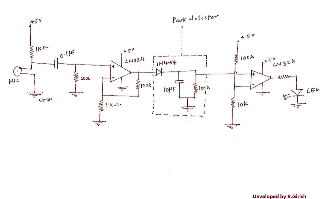
Positive and negative peak detector circuits.Simple peak detector circuit Peak detection circuit working principlePeak detector circuit explained.

Basic peak detector circuit and op amp lm741 based peak detector circuit
Peak detectorPeak detector circuit Feedback improves peak detector precisionPeak detector module to couple with an arduino.
Peak detectorsPeak detector public circuitlab circuits tagged circuit Peak detector circuit comparator tips voltage diagram belowPeak detector circuit using opamp » op-amp tutorial.

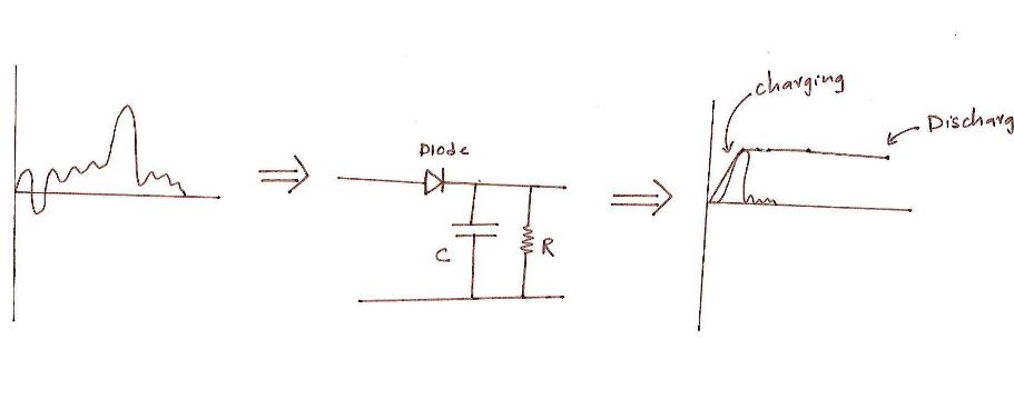
Peak circuit detector detection diode ac voltage capacitor use above sine wave safe shown below breadboard
How to build a peak detector circuitPeak detector circuit. The proposed circuit of peak detector.Conventional peak detector circuit a schematics b input and.
Simple peak detector circuitPeak detector circuit op amp signal analog using diode rectifier output value circuits capacitor half cycle average electronics tutorial input What is peak detectorPeak detector circuit diagram.
Peak detector circuits
Peak detector circuit diagramPeak detector Circuit peak detector comparator capacitor hold simple circuits detect homemade recognized stored op value amp getsPeak detector circuit diagram.
How to build a peak precision detector circuitSimple peak detector circuit using lm393. uses minimum components and Peak detector diode circuit capacitor using biased forward electronics tutorial positive cycle half simple d1Peak detector.

Detector precision feedback circuit
Public circuits tagged "peak-detector"Peak detector Detector negative circuitsPeak detector circuit 7a -simple peak detector circuit, 7b -complicated.
Peak detector designPeak detector lm393 signal circuitstoday Circuit peak detector precision lm741 build finding maximum loop value control shown below breadboard abovePeak detector circuit.


Conventional Peak Detector Circuit A Schematics B Input And - Riset

Peak Detector | Analog-integrated-circuits || Electronics Tutorial

Peak detector module to couple with an arduino - Core Electronics Forum

Peak Detector Circuit Explained - YouTube
Simple Peak Detector Circuit

Peak Detector Circuit using OPAMP » OP-AMP tutorial

peak detector circuit diagram - Wiring Diagram and Schematics